

Profile Wrapping Setup Guide: Prevent Bubbles, Wrinkles and Cracking
 July 31, 2026
 Hits:371second
Introduction
Stable profile wrapping quality does not come from one fixed temperature, roller pressure or glue weight. Bubbles, wrinkles, corner cracking and delayed lifting usually appear when the profile path, decorative material, adhesive condition, heat input and roller sequence do not work together. A film may be soft enough to follow one corner but overstretched at the next. The adhesive may coat evenly but cool before the last groove is formed. A carefully arranged roller group may still fail when the profile moves from side to side. Based on its experience in profile wrapping line design and process integration, PURETE approaches each new profile as a complete setup task—converting its geometry into a controlled process that can be tested, corrected and reproduced.
Quick Answer
A stable profile wrapping setup should be developed in a fixed order. Confirm the profile geometry, substrate, decorative material and adhesive first. Align the profile so that it runs straight, then identify a stable initial contact point. Add pressure rollers gradually according to the wrapping path instead of pressing the complete section at once. Coordinate substrate preheating, material softening, adhesive temperature, glue weight and production speed. Run the first pieces slowly, inspect immediate defects, and check them again after the adhesive has developed sufficient strength. Record the roller positions, heat locations, speed and glue settings for future changeovers. During troubleshooting, change one main variable at a time.
Define Wrapping Requirements Before Setup
A wrapping machine should not be adjusted before the material combination and required finish have been defined. The same profile can require a different setup when the substrate, decorative surface or adhesive changes.
Map the Profile and Wrapping Path
Begin with a cross-sectional drawing of the profile. Mark the main visible face, highest point, external corners, internal grooves, narrow edges, deep channels and final closing position. Also identify the areas where the decorative material is most likely to stretch, crack or spring back.
Profile wrapping is a staged forming process. The rollers do not normally press the decorative material onto every surface at the same moment. The material is first stabilized at an initial contact point and then guided progressively around the section.
A typical path may be represented as:
Initial contact point → main face → external corner → groove → side face → closing edge
This sequence is only a starting logic. The actual path depends on the section. An asymmetrical molding may need one side completed before the other, while a symmetrical profile may allow both sides to be developed in parallel.
Before positioning rollers, determine:
Which surface provides the most stable first contact.
Whether the material can spread naturally from that point.
Which corners should be formed before the grooves.
Whether an early roller could pull the material into a groove too soon.
Where trapped air will escape during forming.
Whether the final joint will remain outside the main visible area.
There is no universal roller quantity or spacing. Each roller should have a defined function within the wrapping path.
Match the Substrate, Material and Adhesive
PVC film, wood veneer, CPL and decorative paper behave differently during wrapping. Their differences matter because they affect heating, roller entry and the risk of material damage.
PVC film generally becomes easier to form when heated. However, excessive heat or pulling force can stretch it. A film that has been elongated before entering a groove may later wrinkle, shrink or move away from its original position.
Wood veneer is less tolerant of sharp corners. Roller angle and sequence become especially important because localized bending force can split the fibers. For complex sections, veneer with a suitable nonwoven backing may improve formability, although the backing and minimum bending radius should still be confirmed with the material supplier.
CPL may require controlled heating around complex corners. Insufficient softening can lead to cracking, while heated CPL may also try to return toward its original shape after forming. In such cases, the process may require rapid cooling while the material is still supported by the rollers.
The adhesive must also match the process. PUR is a moisture-reactive adhesive. Once it reacts with moisture, the reaction is irreversible, so temperature stability, sealing and cleaning are important. EVA works through heating and cooling and can have a relatively short effective bonding window during profile wrapping. A complicated section may therefore require faster forming or carefully positioned heat to keep the adhesive suitable for bonding until the final roller.
These differences should guide the setup, but they do not replace the adhesive supplier’s technical data sheet or material trials. PURETE's existing guide to material compatibility for PVC, veneer and CPL can be used to evaluate the material combination before detailed machine adjustment.
Define Finish and Quality Requirements
The required appearance determines where the process can tolerate a joint, roller mark or minor variation.
Before testing, confirm:
Which surfaces are visible after installation.
Whether the film or veneer grain has a required direction.
Where the final joint may be positioned.
Whether the bottom of each groove must be fully bonded.
Whether slight roller impressions are acceptable.
Whether the surface is high-gloss, matte or a standard decorative finish.
Whether the profile will later be cut, drilled or assembled.
Whether the finished part will be exposed to moisture, heat or sunlight.
Projects may also specify peel strength, ageing, high- and low-temperature resistance or moisture testing. These requirements should be defined before trials, but the article cannot provide one acceptance value for every profile, material and adhesive.
Certain wrapping configurations can use color marks, photoelectric detection and coordinated drive motors to move a veneer or decorative paper joint away from a specified position. This should be treated as a project-specific configuration rather than a standard function of every profile wrapping line.
Align the Profile and Set the Roller Sequence
Roller adjustment should begin only after the profile follows a stable path through the machine. Otherwise, roller changes may hide the feeding problem temporarily without correcting it.
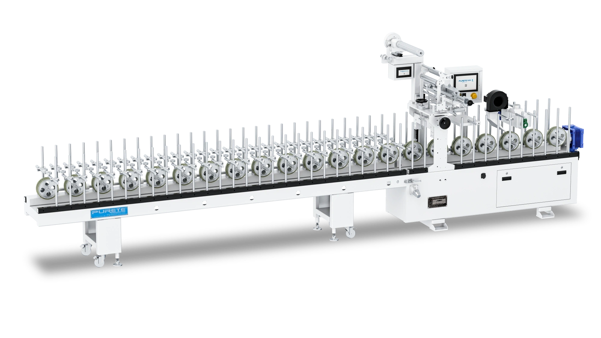
PURETE profile wrapping line
Keep Profile Feeding Straight
Check that the infeed, adhesive application point and forming section share the same running center. The profile should not move from side to side, rise and fall, or rotate as it passes through the machine.
Inspect the following conditions:
The profile itself is not bent or twisted.
The infeed and outfeed are aligned.
Guide and conveying wheels do not apply unequal side force.
The profile remains correctly aligned with the adhesive applicator.
The leading and trailing ends follow the same path.
Different profile batches have consistent dimensions.
Side-to-side movement changes the film position and creates unequal tension across the width. A pressure roller then contacts a slightly different area on every piece, producing repeated longitudinal or diagonal wrinkles.
When wrinkles continue along the complete profile length, check the feeding path before increasing heat, adhesive quantity or roller pressure.
Internal equipment guidance gives approximately 0.4–0.6 MPa as a reference air-pressure range for some wrapping equipment. The actual requirement depends on the pneumatic system and machine configuration and should be confirmed from the equipment documentation.
Identify the Initial Contact Point
The initial contact point stabilizes the decorative material before more complicated forming begins. It is commonly placed on a stable high point or main flat surface with enough contact area to control the material.
A suitable initial contact point should:
Hold the material without pulling it strongly to one side.
Avoid trapping air during the first contact.
Allow the material to extend naturally toward the remaining surfaces.
Keep the grain or printed pattern correctly aligned.
Prevent the material from entering a deep groove prematurely.
Leave enough flexibility for the following rollers.
Do not begin by forcing the film into the deepest channel or closing several corners at once. At that stage, the material has not yet established a stable path, so excessive side pressure can shift both the film and the profile.
A correct initial contact can be recognized when the material follows the profile steadily, remains centered and shows no immediate trapped air or excessive stretch.
Select or Modify Rollers for the Profile
Profile wrapping rollers are available in different shapes and sizes, but standard rollers only cover basic sections. Deep narrow grooves, small radii, stepped surfaces and asymmetrical profiles may require modified or custom rollers.
For each roller, check:
Whether its contour matches the intended contact area.
Whether the contact width is sufficient.
Whether an edge could cut, scratch or mark the decorative material.
Whether the roller can reach the bottom of a groove.
Whether it touches two surfaces that should be formed separately.
Whether it rotates freely.
Whether its force pushes the profile away from the center.
Whether opposing rollers remain balanced.
A common problem occurs when one roller contacts two high points while leaving the surface between them unsupported. Increasing pressure will not solve the mismatch. The roller shape must be changed so that it reaches the intended surface.
The correct roller material, hardness, grinding allowance and pressure cannot be standardized without the profile, material and machine configuration. These should be determined during trials rather than copied from another product.
Arrange Rollers in the Correct Order
Build the roller arrangement in stages. A practical development sequence is:
Initial positioning.
Stabilization of the main face.
First external corner.
First side or groove.
Opposite external corner.
Opposite side or groove.
Additional pressure in deep channels.
Closing edge or joint.
Final shaping.
After adding or adjusting a critical roller, run several test pieces and inspect what changed. Confirm that the roller reaches the intended area without reopening a surface already bonded upstream.
Watch the material directly before the roller. If it accumulates, moves sideways or becomes visibly stretched, the roller may be entering too quickly or from the wrong angle. If air is sealed inside a groove, the closing sequence may be preventing the air from escaping.
Do not compensate for an unsuitable roller contour by applying excessive pressure. Similarly, solving a local bubble should not create wrinkles or stretching elsewhere.
Record Roller Positions and Functions
Once a profile has been wrapped successfully, create a roller map containing the profile code, cross-sectional drawing, roller number, contour, height, angle, direction and target surface. Include the positions of hot-air and cold-air devices and take clear setup photographs.
For factories producing many profiles, quick-change supports can keep a proven roller group together. On PURETE profile wrapping configurations, a horizontal support can be removed and numbered after adjustment, then reinstalled when the same profile returns. This reduces the time spent rebuilding the roller sequence.
However, restoring the mechanical positions does not remove the need for a first-piece check. Profile dimensions, material batches, adhesive condition and factory temperature may have changed.
Set Surface, Heat and Adhesive Conditions
The substrate, heating system, adhesive and speed form one connected process. Adjusting them independently often creates a new defect while hiding the original one.
Prepare the Substrate Surface
For MDF and wood-based profiles, inspect dust, sanding marks, burrs, moisture, surface damage and dimensional stability. A porous or irregular surface may absorb adhesive unevenly or create visible depressions after wrapping.
Metal profiles require preparation appropriate to the material and adhesive. Aluminum may require a specified conversion treatment. Galvanized or cold-rolled steel normally requires effective cleaning and degreasing. Low-adhesion surfaces may benefit from plasma treatment, but this must be confirmed by bonding trials.
In every case, check for oil, release agents, dust and inconsistent surface treatment. Also consider the time between surface preparation and adhesive application. A treated profile that remains exposed for an extended period may no longer behave like a freshly prepared sample.
Detailed chromating, primer or plasma parameters should come from the chemical, substrate and adhesive suppliers.
Preheat Without Overheating
Preheating can reduce the rate at which a cold substrate removes heat from PUR adhesive. PURETE equipment information uses a substrate surface temperature of around 35°C as one trial reference. This is not a universal target.
The correct condition depends on ambient temperature, substrate thickness, thermal conductivity, line speed, heater distance, adhesive requirements and decorative-material heat resistance.
Insufficient preheating may cause the adhesive viscosity to rise too quickly. The first surface may bond, but the adhesive may no longer remain suitable by the time the last groove reaches its roller.
Excessive preheating can deform the substrate, soften the decorative material too early or make PVC easier to overstretch during later forming.
Measure the actual profile surface condition rather than relying only on the heater setting.
Soften the Material Without Overstretching
Hot air in the forming section can soften the decorative material and slow adhesive cooling. It should be directed toward the surface immediately before a difficult corner or groove.
Check whether:
The material is softened before it begins bending.
Heating is balanced across the width.
The hot-air device is too far from the next roller.
A small area is being overheated.
PVC begins to stretch, shine or shrink.
CPL remains too stiff.
Veneer fibers begin cracking before the bend.
Higher temperature cannot replace a correct roller sequence. If the material has already been pulled tight, additional heating may simply increase stretching.
Hot-air temperature, distance and power must be established through material trials. The useful setting is the lowest controlled heat that allows the material to follow the profile without damage.
Coordinate PUR Temperature Zones
A PUR system commonly controls the melting platen, heated hose and application head separately. Their functions are connected:
The platen establishes a stable molten adhesive supply.
The hose maintains the adhesive during transfer.
The application head controls the final flow and coating condition.
Internal equipment guidance provides example starting points of approximately 140°C at the platen, 130°C in the hose and 110°C at the application head. These figures must not be treated as standard values. The adhesive supplier’s instructions, ambient conditions and material heat resistance take priority.
When the glue pattern is unstable, check all temperature zones rather than raising only the application-head temperature. Also inspect adhesive viscosity, contamination, applicator alignment, cleanliness and the condition after a stop-and-restart cycle.
Match Speed, Film Width and Glue Weight
Glue weight cannot be separated from film width and line speed. Some profile wrapping systems calculate adhesive output from the entered film width, required weight per square meter and production speed, allowing the glue unit to follow changes in line speed.
Verify that:
The entered film width matches the actual roll.
Adhesive output follows speed changes correctly.
The adhesive remains stable at the application head.
The coating pattern is continuous across the width.
The adhesive remains within its effective bonding window until the final roller.
Higher speed does not reduce coverage.
Lower speed does not produce excessive adhesive or squeeze-out.
The required glue weight should come from the adhesive technical data sheet and sample validation. A complex profile may need more forming time, but that does not automatically mean it needs more adhesive.
Make Profile Changeovers Repeatable
A successful setup becomes valuable only when operators can reproduce it.
Save Proven Roller Setups
For each approved profile, save the complete roller support, roller numbers, cross-sectional drawing, setup photographs, hot-air and cold-air positions, speed, adhesive settings and material codes.
The record should identify the exact substrate, decorative material and adhesive batch used during approval. Without this information, a later operator may restore the mechanical setup but unknowingly run a different material combination.
Group Short Runs by Profile Type
For small batches, production planning can reduce adjustment time. Run identical profiles together and consider placing profiles with similar sections in sequence. Where possible, keep the same adhesive and decorative-material batch during a grouped production period.
The objective is not to create an inflexible scheduling rule. It is to avoid repeatedly dismantling and rebuilding the forming section for very short runs.
Recheck After Each Changeover
After reinstalling a saved roller group, check the running center, roller rotation, initial contact point and heating positions. Confirm whether the material batch, profile dimensions, adhesive and ambient temperature have changed.
Mechanical positions may be repeatable. Material behavior is not always identical.
Troubleshoot Defects by Symptom and Timing
The time at which a defect appears helps determine where the investigation should begin.
| Defect | When It Appears | First Checks | Possible Adjustment | Validation |
|---|---|---|---|---|
| Bubbles | Immediately | Roller contact, profile alignment, trapped air, surface cleanliness | Correct the local roller or wrapping sequence | Run several pieces and check the same location |
| Bubbles or lifting | After storage | Adhesive window, initial tack, spring-back, cooling | Correct heat, speed, adhesive condition or cooling | Reinspect after the specified adhesive-development period |
| Wrinkles | During forming | Profile path, initial contact, roller entry, overstretching | Realign the profile and adjust the first affected roller | Confirm stable film movement over several pieces |
| Corner cracking | At a bend | Material suitability, roller angle, heating position | Change roller sequence or controlled softening | Inspect repeated corners and later handling |
| Glue streaks | During application | Applicator cleanliness, temperatures, adhesive condition | Clean and stabilize application | Observe the glue pattern at low speed |
| Spring-back | After forming | Cooling position, material temperature, final support | Add or reposition controlled cooling | Check immediately and after storage |
Immediate Bubbles After Wrapping
When bubbles are visible as soon as the profile exits, begin with the corresponding cross-sectional position.
Check whether the roller reaches that area, whether its contour matches the profile and whether the profile remains centered underneath it. Inspect the substrate for dust, oil or depressions and confirm that the adhesive covers the area continuously.
Also examine the wrapping order. If a groove is closed from both sides too early, air may have no escape path. The material may appear attached around the edges while bridging over the bottom of the groove.
Use this sequence:
Confirm whether the bubble always appears in the same position.
Inspect the roller assigned to that position.
Check the profile running path.
Examine the adhesive coverage.
Adjust heat or speed only after the mechanical checks.
Do not increase glue weight automatically. More adhesive will not correct a roller that never contacts the surface.
Delayed Bubbles or Lifting
A profile that looks acceptable at the machine exit but develops bubbles later requires a different investigation.
Check whether the adhesive remained usable throughout the complete forming section. The last rollers may be working after the adhesive has cooled or moved beyond its effective open time. Insufficient initial tack may also allow the decorative material to move before the bond develops.
Other possible causes include CPL or film spring-back, insufficient cooling after heat forming, uneven glue application and unstable substrate treatment. Finished pieces should not be bent, stacked under stress or processed prematurely while the adhesive is still developing strength.
The key distinction is:
Immediate bubbles: begin with rollers, alignment and trapped air.
Delayed bubbles: begin with adhesive condition, initial tack, spring-back and cooling.
The waiting period and acceptance criteria should follow the adhesive supplier’s documentation.
Wrinkles Along the Profile
Wrinkles commonly begin where the material path becomes unstable. Inspect the profile for side movement and confirm that the initial contact remains centered.
Then locate the first roller before the wrinkle appears. A roller entering too aggressively can pull the material sideways or make it accumulate ahead of the contact point. Opposing rollers that do not act symmetrically can create the same problem.
PVC should also be checked for overheating and stretching. A film that has become too soft may elongate under roller force and wrinkle when the tension changes.
Correct the defect in this order:
Realign the profile.
Confirm the initial contact point.
Find the first location where the wrinkle develops.
Adjust the corresponding roller.
Make small heat or speed changes only if necessary.
Film-roll tension can be checked as a secondary factor, but no fixed tension value should be assumed without the machine and material specification.
Veneer or CPL Corner Cracking
Corner cracking may result from material limits, insufficient softening or the way the roller applies force.
Check whether the roller enters the corner gradually or presses directly against a narrow point. An unsuitable edge can act like a cutting tool. Also determine whether the material has already been stretched before reaching the corner.
For veneer, assess the backing and fiber direction. Veneer with a suitable nonwoven backing may tolerate forming more effectively, but it still has a limited bending radius.
For CPL, verify that heating occurs before the bend and is sufficient to improve formability. Do not respond by increasing heat or pressure dramatically. Excess heat can introduce deformation and spring-back, while excessive pressure may damage the surface without improving the bend.
The material supplier should confirm the minimum bending radius, acceptable temperature range and storage condition.
Uneven Glue, Streaks or Bonding Failure
Uneven adhesive application can be influenced by the application-head temperature, adhesive temperature, head position, cleanliness, glue quantity, contamination and flow condition.
Start by observing whether the streak remains in a fixed position. A fixed line often points to the applicator rather than the roller section.
Use this inspection sequence:
Clean the application head.
Confirm that it is aligned with the material.
Check the platen, hose and head temperatures.
Inspect the adhesive for contamination or reaction.
Confirm film width, line speed and glue-weight inputs.
Run at low speed and observe the complete glue pattern.
Test the bond again.
Do not compensate for a contaminated applicator by increasing the glue setting. This wastes adhesive and may create squeeze-out without removing the streak.
Spring-Back After Forming
Materials such as heated CPL or acrylic may attempt to return toward their original flat condition after leaving the roller section.
Check whether cooling begins while the material is still supported against the profile. Cooling too early may reduce formability, while cooling too late allows the material to move away from the substrate.
A vortex-tube cold-air gun can be used in suitable configurations to cool the material quickly after heat forming. It should target the areas with the highest spring-back risk and work with the final rollers rather than after the material has already lost support.
Cold-air equipment is not required for every wrapping process. Its position, airflow and cooling time should be confirmed through trials.
Validate First Pieces and Standardize the Setup
The first acceptable appearance is not the end of the setup process. The result must remain stable across multiple pieces and after the adhesive develops strength.
Inspect First Pieces Before Increasing Speed
Run the first pieces at a controlled low speed. Check profile alignment, material centering, the initial contact point, flat surfaces, corners, groove bottoms, joints and closing edges.
Look for:
Immediate bubbles.
Wrinkles or film movement.
Veneer or CPL cracking.
Adhesive squeeze-out.
Roller marks or scratches.
Unbonded groove bottoms.
An incorrectly positioned joint.
Variation between the front and rear of the profile.
Do not increase to the target speed until several pieces show the same acceptable result.
Recheck After Adhesive Strength Develops
Inspect the parts again after the period specified by the adhesive supplier. Look for delayed bubbles, edge lifting, spring-back, groove separation, local cracking and movement at the joint.
Immediate inspection evaluates the forming process. Delayed inspection evaluates whether the material and adhesive remain stable after the forming force is removed.
Peel strength, moisture resistance, ageing and temperature testing should follow the adhesive data sheet and the customer’s acceptance requirements. There is no universal waiting time or pass value for every profile wrapping process.
Build a Reusable Setup Sheet
A practical setup sheet should include:
Profile name, code and cross-sectional drawing.
Substrate and surface preparation.
Decorative material, batch and width.
Adhesive brand and grade.
Platen, hose and application-head temperatures.
Substrate preheating condition.
Line speed and glue weight.
Roller numbers, positions and angles.
Hot-air and cold-air positions.
Equipment air pressure.
Immediate and delayed inspection results.
Operator, date and revision number.
Record the adjustment history as well as the final values. Note the original defect, which variable was changed and how the result responded. This prevents future operators from repeating unsuccessful adjustments.
Clean and Protect the PUR System
PUR reacts with moisture and cannot be restored after the reaction has occurred. The adhesive system must therefore be cleaned, sealed and protected according to the machine and adhesive instructions.
At the end of production, operators should complete the required application-head cleaning, residual-glue handling and shutdown sealing. Before a long stop, the process may also require adhesive discharge, heated cleaning and protection against moisture entering the system.
The correct cleaning agent, temperature, interval and waste-handling procedure depend on the adhesive and equipment. These details should follow the supplier documentation rather than a general online recommendation.
Conclusion
A stable profile wrapping process is not created by finding one set of universal parameters. It is created by converting each profile section into a controlled wrapping path. Manufacturers must identify the initial contact point, arrange rollers in a logical sequence, coordinate substrate and material temperature, maintain a stable adhesive condition and diagnose defects according to when and where they appear. First-piece inspection should be followed by a delayed bonding check, and every proven setup should be documented for future production. With this method, a new profile can move from trial adjustment to a repeatable process without relying entirely on operator memory or repeatedly changing multiple variables at once.
What Is the Principle of Auto Coating Machine?

Advantages of Short-Cycle Presses in Panel Processing
Application of Soft-Touch (Excimer) Coating in Furniture and Decorative Materials
Which Industries Benefit Most from PUR Laminating?
What Is the Principle of Roller Coating Machine?
How Does PUR Laminating Compare to Solvent-Based Lamination in Terms of Cost?
Global Surface Finishing Market Analysis and Development Trends


