

How to Design a Chemical Milling Maskant Spray Line for Aircraft Components
 September 30, 2026
 Hits:16second
Chemical milling is not a conventional paint-finishing operation. The maskant is applied before selected metal areas are exposed to an etchant, while the areas that remain covered are protected through that downstream process. That role changes the design question. A line cannot be specified simply by choosing a spray machine and adding a conveyor. It has to control how the approved maskant reaches the part, how the part is supported and handled, how each layer reaches its required state, and how the coated component moves into inspection and the next chemical-milling step.
For an aircraft-component project, the right starting point is therefore the workpiece and the approved process—not an existing paint-line layout. As a manufacturer of automated coating and finishing production lines, PURETE uses those inputs to define the automation concept. A reciprocating or robotic spray module may be part of the answer, but it is only one part of a controlled maskant application route.
Why a Chemical Milling Maskant Line Is Not a Standard Paint Line
Chemical milling selectively removes metal from exposed areas. A maskant remains where the metal must be protected, then is removed from the areas intended for milling. Public aerospace-process guidance describes maskants as rubber- or polymer-based coatings that may be applied by brushing, dipping, spraying, or flow coating. Spray application is useful when the part, process window, and production rhythm support it, but it is not automatically the right method for every component.
The difference matters because a decorative finish is normally judged by appearance and finish performance. A chemical-milling maskant must instead fit a linked process: application, layer development, inspection, selective removal or scribing where required, chemical milling, and final removal. A visually acceptable coat is not by itself proof that the maskant is ready for the next operation.
The material data approved for the program should define the application and drying window. The line should then make that window repeatable. This is more useful than treating a generic paint setting as a universal target for every maskant, alloy, or part shape.
Start with the Part, the Approved Maskant, and the Chemical-Milling Route
Before choosing spray motion, collect the design inputs that actually change the equipment route:
- part dimensions, curvature, openings, ribs, and areas that cannot be safely supported from the visible surface;
- substrate and surface-preparation sequence;
- the approved maskant's SDS, technical data, mixing and application instructions;
- one-side or two-side treatment, plus the permitted handling and turnaround path;
- required layer sequence, intercoat condition, cure or flash-off requirements, and inspection method;
- the downstream interface to scribing, selective maskant removal, chemical milling, cleaning, and demasking; and
- the facility utilities and EHS engineering conditions that govern the installation.
This list is not a procurement formality. It determines whether a part should travel on a supported conveyor, be held in a dedicated fixture, enter a rotation or flip station, or return through the same application zone. It also determines whether a broad, repeated spray pattern is suitable or whether local contours need a more adaptable path.
For example, a flat component may allow a predictable conveying and spraying sequence. A curved or structurally detailed component may make fixture access, shadow areas, edge control, and safe transfer the dominant design issues. The equipment layout must follow those conditions rather than assuming that a panel-handling arrangement can be transferred unchanged to an aircraft part.
Build the Spray Section Around Repeatable Coverage and Layer Control
The objective of the spray section is repeatable, inspectable coverage within the approved material window. That objective involves more than the time spent under the guns. It includes material preparation, feed stability, part positioning, motion path, spray-zone containment, layer-to-layer handling, and the ability to isolate a part that needs rework.

Automated spray-booth interior illustrating the application zone and workpiece path. Explore PURETE automated spray-line modules
The approved maskant instructions should govern how the supply system is prepared, mixed, filtered, circulated, or cleaned. A line builder can provide the appropriate material-handling modules once those instructions are known; it should not substitute a generic coating recipe for the material supplier's process requirements.
Choose Motion from the Geometry of the Part
Reciprocating spray technology can be a practical option where the workpiece presents repeatable areas and a controlled travel path. Its value is a consistent, programmable relationship between spray path and conveyed part. Robotic or other programmable motion can become more relevant when part geometry, local features, or access constraints require a path that is not well represented by a repeatable traverse.
The decision is not a contest between machine types. It is a question of whether the selected movement can reach all required surfaces while keeping the fixture, transfer method, and coating path under control. For a two-sided component, the design may use a controlled flip operation, separate fixtures, or a defined return route. Each alternative should be checked against the material's permitted handling state and the risk of touching or contaminating the coated surface.
In a chemical milling maskant project, PURETE approaches workpiece fixtures, automated spray motion, conveying, extraction, and cleaning interfaces as automated spray-line modules within one controlled application route. Their final arrangement should be defined against the part geometry, approved maskant data, and required process route—not assumed from a standard furniture or panel spray line.
Design for Verification, Not Only for Spray Time
Coverage verification should have an explicit place in the line layout. The required inspection method comes from the component's process specification, but the equipment plan should make inspection possible: allow safe access to the part, maintain identification through the route, define where nonconforming pieces leave the main flow, and avoid sending an unverified part into the next operation.
The same principle applies to layer control. If the approved process requires repeated application with a defined intermediate condition, the line needs a real physical and scheduling answer: a staged section, a controlled return path, a buffer, or a separate operation. Treating that interval as an informal wait beside the conveyor makes the process harder to reproduce and harder to audit.
Connect Spray, Flash-Off, Inspection, and Downstream Chemical Milling
The spray booth is only one interface in the manufacturing route. The project should map what happens immediately before and after it.
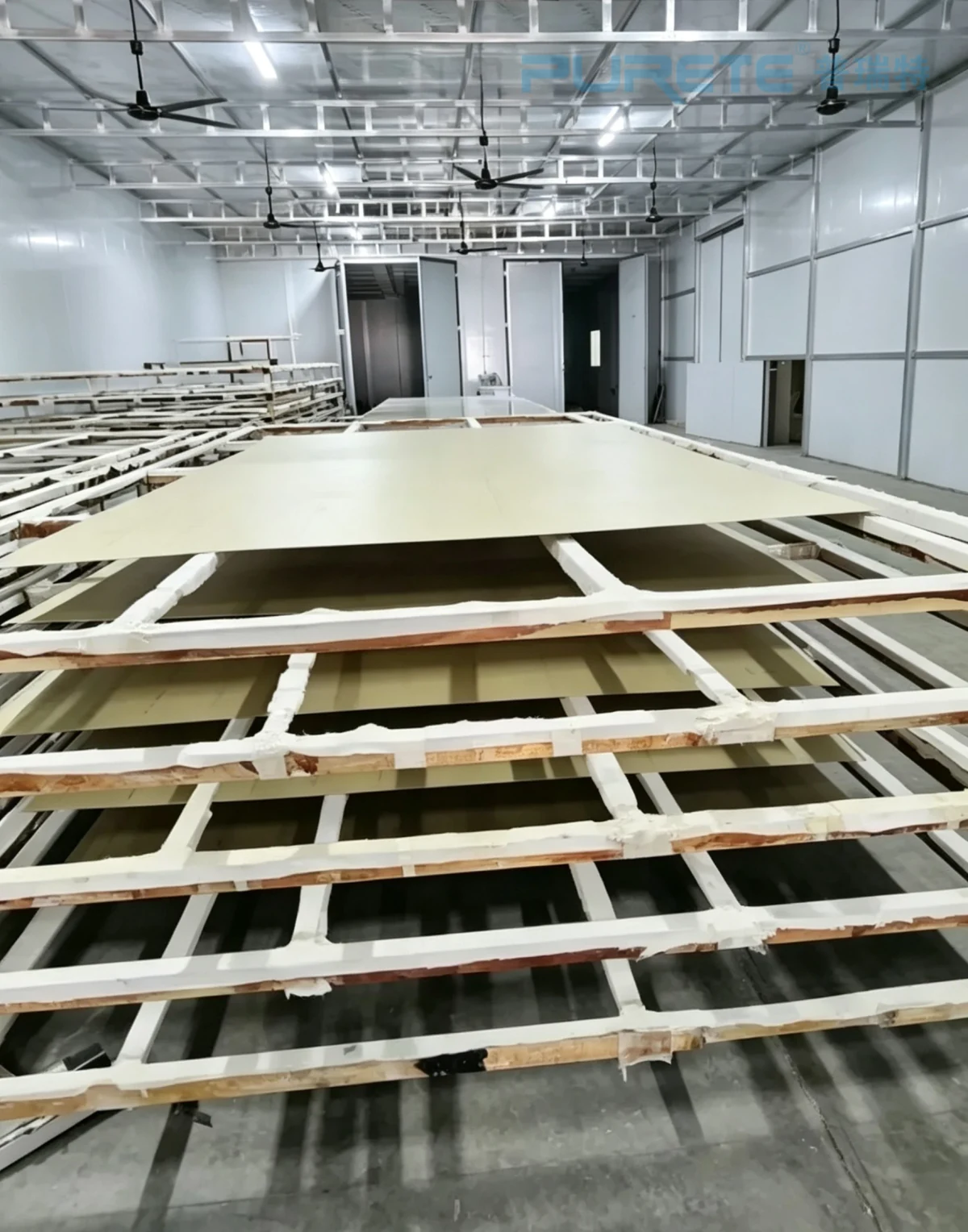
Panel staging and transfer area illustrating the handoff between application and downstream operations.
Upstream, the team should establish how the component arrives clean, identified, and supported without creating inaccessible areas. In the spray zone, the part must remain positioned consistently enough for the programmed path to be meaningful. After application, the line needs a defined handoff to the applicable layer-development, inspection, and downstream chemical-milling steps.
This route is also where contamination control becomes practical. A clear separation of material preparation, application, handling, inspection, and cleaning prevents the line from relying on ad hoc movement or shared tools. The exact layout will vary with the approved material, the workpiece, and the factory plan, but the design principle is stable: every transfer must preserve the condition that the next process assumes.
Define the Environmental, Fire, and Process-Safety Boundary Early
Many chemical-milling maskants have historically used volatile solvent constituents, and public aerospace-process guidance identifies solvent evaporation during application and cure as an engineering consideration. That is enough reason to bring EHS and qualified facility engineers into the project at the concept stage.
The spray-line supplier can define the equipment interfaces that need coordination: enclosure, extraction connection points, material-transfer boundaries, access, cleaning arrangements, controls, and information exchanged with facility systems. The customer and competent EHS, electrical, fire-protection, and process specialists must determine the applicable chemical handling, ventilation, hazardous-location, fire-protection, emissions, and waste requirements for the actual maskant and installation.
This division of responsibility makes the project stronger. It avoids presenting a generic electrical classification, exhaust rate, alarm point, abatement technology, or disposal route as if it were correct for every material and jurisdiction. Those decisions belong to the applicable SDS/TDS, local rules, and qualified project engineering.
A Practical Design-Input Checklist for the Equipment Project
| Design area | Input to provide | Equipment decision it unlocks |
|---|---|---|
| Part | Drawing, size range, geometry, weight, supported surfaces, and batch mix | Fixture, conveyor, transfer, rotation, and access concept |
| Material | Approved SDS/TDS and application instructions | Compatible material handling, cleaning, application, and layer-control concept |
| Process | Surface preparation, layer sequence, intermediate state, inspection and downstream handoff | Number and order of stations, buffers, return route, and quality gates |
| Quality | Acceptance criteria, traceability needs, rework route | Inspection access, identification, reject isolation, and records interface |
| Facility | Available utilities, layout, EHS and electrical/facility engineering requirements | Enclosure, extraction, controls, and installation interfaces |
With these inputs, the discussion can move from “Which spray machine should we buy?” to “Which controlled process route should this component use?” That is the level at which equipment scope, responsibility, and validation planning become clear.
Conclusion: Treat the Maskant Line as a Controlled Process Interface
A chemical-milling maskant spray line should be designed as part of the chemical-milling route, not as an isolated paint booth. Start with the component and its approved maskant. Use those inputs to select workpiece handling, motion, material supply, layer control, inspection, and the handoff to downstream operations. Then coordinate the facility and EHS engineering boundaries before the layout is frozen.
For aircraft components, that sequence is more reliable than adapting a general spray line from its machine list outward. It keeps the automation focused on what the process actually needs: controlled application, controlled handling, and a verifiable path to the next manufacturing step.
Plan a Maskant Application Route with PURETE
To start the discussion, contact PURETE and share the part size range and geometry, the approved maskant SDS/TDS, the target process sequence, and the available factory conditions. PURETE can use those inputs to discuss an automation concept for handling, application movement, conveying, and inspection interfaces that can be reviewed with your process and EHS teams.
FAQ: What Should Be Confirmed Before Ordering a Maskant Spray Line?
Can an existing paint line be reused?
Possibly, but only after the approved maskant, component handling, cleaning requirements, inspection route, and facility engineering conditions have been compared with the existing line. Similar spray motion alone is not enough to establish process suitability.
Which spray settings should be specified first?
Use the approved maskant material instructions and component process specification first. They establish the applicable application and layer-control window. Equipment settings should be selected to reproduce that window, not copied from an unrelated coating process.
When should EHS and electrical specialists join the project?
At concept stage, before enclosure, extraction, controls, and installation interfaces are frozen. Their review should be based on the actual material documentation, site conditions, and applicable local requirements.
What Is the Principle of Auto Coating Machine?

Advantages of Short-Cycle Presses in Panel Processing
Application of Soft-Touch (Excimer) Coating in Furniture and Decorative Materials
Which Industries Benefit Most from PUR Laminating?

What Is the Principle of Roller Coating Machine?
How Does PUR Laminating Compare to Solvent-Based Lamination in Terms of Cost?
Global Surface Finishing Market Analysis and Development Trends


